1.0 Introduction
This is a short blog post containing a step-by-step guide to convert the Tuya Zigbee Valve battery power supply to a DC/Mains power supply. This upgrade means you no longer need to worry about batteries draining as the device will have a continuous power source for your smart irrigation system. In this guide, I’ll walk you through the process, step-by-step.
2.0 Why Upgrade to Regulated Power Supply?
This was in response to the batteries of these devices draining very quickly and requiring frequent replacements. Upgrading to a regulated power supply ensures a stable and continuous power source, reducing the need for constant maintenance and enhancing the overall reliability of your Zigbee irrigation system.
3.0 Calculating Power Requirements
Before diving into the conversion process, it’s essential to have a basic understanding of how Zigbee irrigation valves work and the power requirements associated with them. Each device is powered by 4x AA batteries in series. Each AA battery is 1.5V at 100%, therefore, the total voltage needed for this device is:
total voltage = 4 x 1.5V
Therefore:
total voltage = 6v
3.1 Current (amps) requirement:
A typical AA battery has a peak current of over 2A. But I know (just from my own experience) that these zigbee devices won’t be drawing that much. So lets say approx 1amp max current during peak demands (and that is being very generous).
4.0 Materials Needed
-
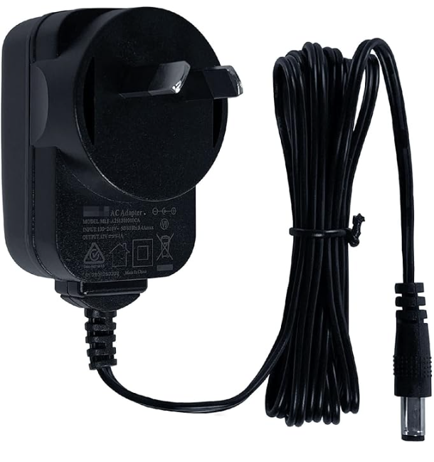
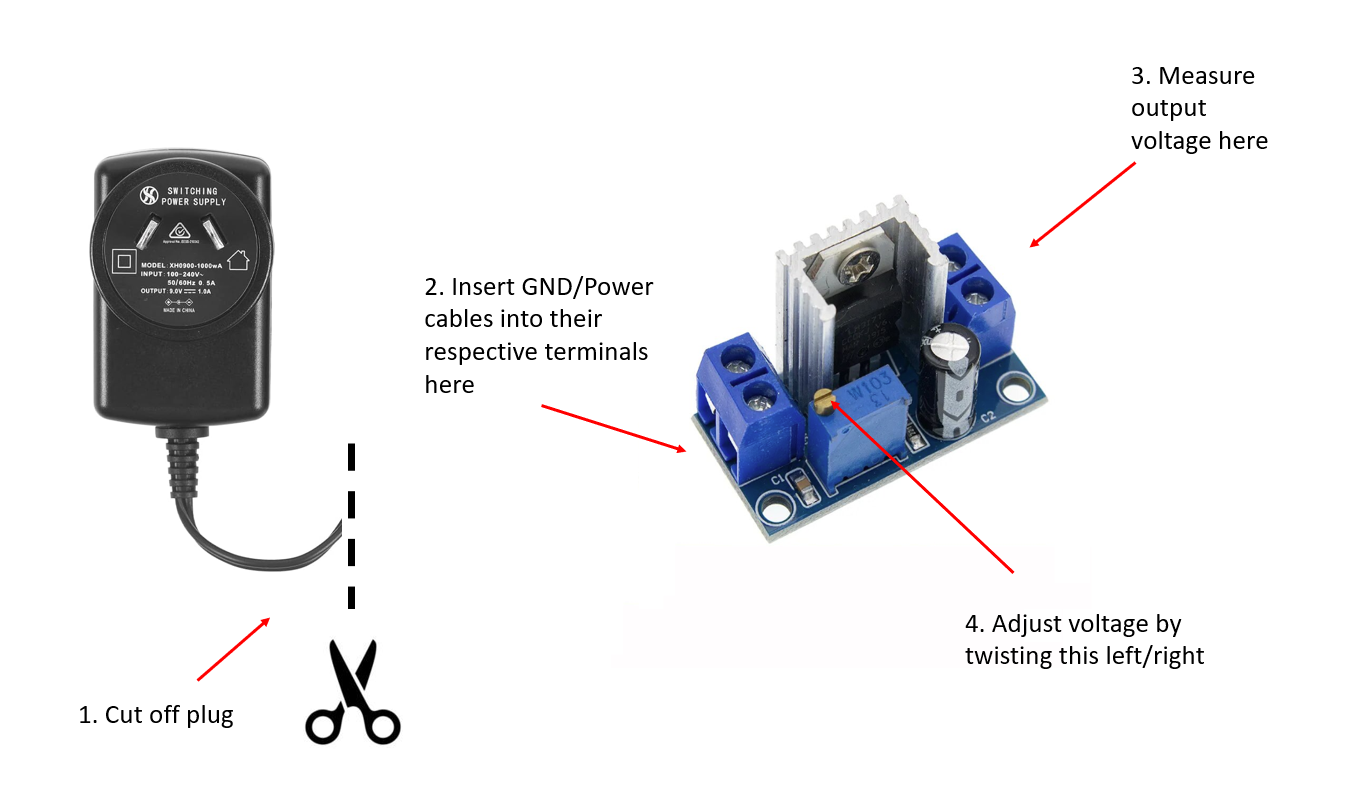
An AC to DC power supply with atleast 6v and 1amp output. Most power supplies are either 5V or 12V. A 5v supply will be sufficient but if you have a 12v supply, you will need a voltage regulator shown in step 2 below. A typical looking power supply is pictured below
-
A linear regulator - only needed if you your power supply has an output greater than 6v. A good example is the LM317 Adjustable Voltage Regulator Power Supply (see image below). Just go to AliExpress and search
LM317 Breakout Board. An example is shown below.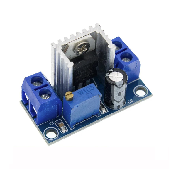
-
A small plastic container to store the linear regulator in (if you need one).
-
A multimetre to check the voltage
5.0 Step-by-Step Process
5.1 Wiring diagram
Shown below is the wiring diagram for the modified and regulated power supply. If you are using a regulator to change the voltage, you will need to tune the regulator output to the required 6v needed for this unit. Use a multimeter to do so.
5.2 Disassembling the device
Begin the conversion process by carefully disassembling the Zigbee irrigation valve. Take note of the existing components and their placements.
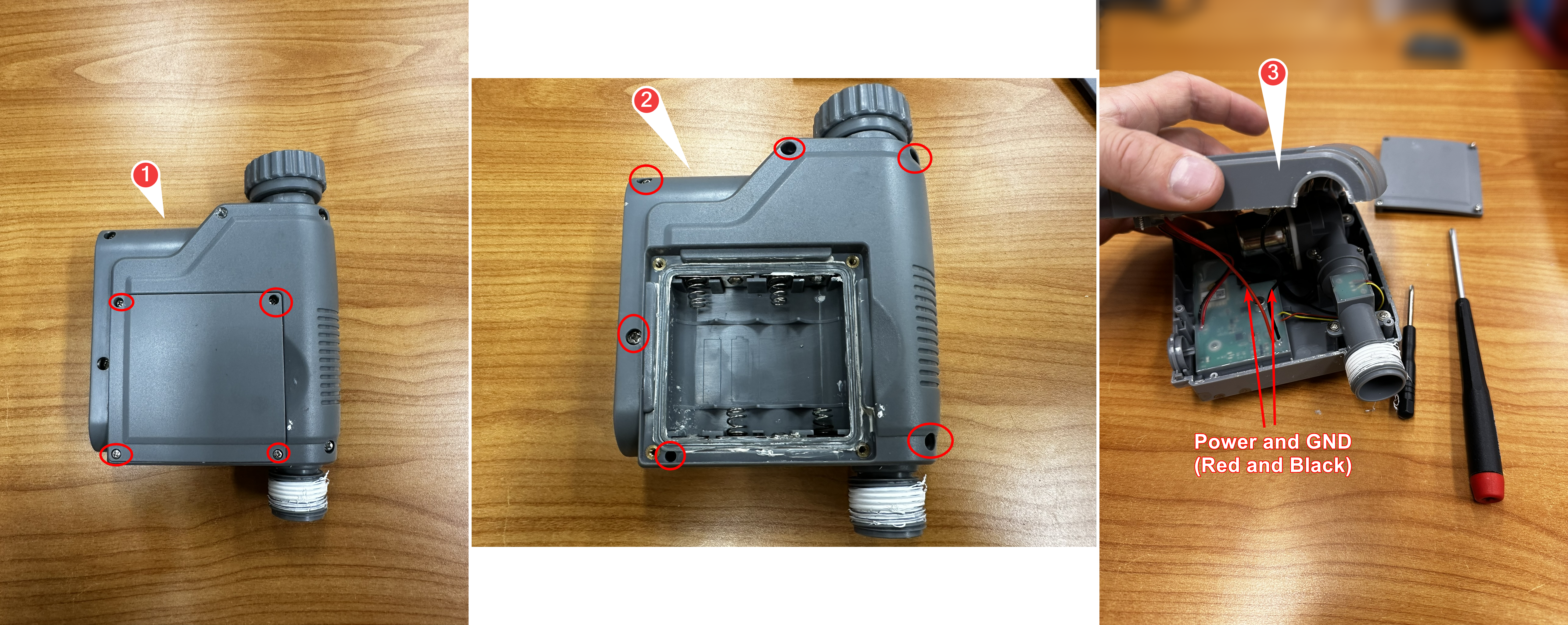
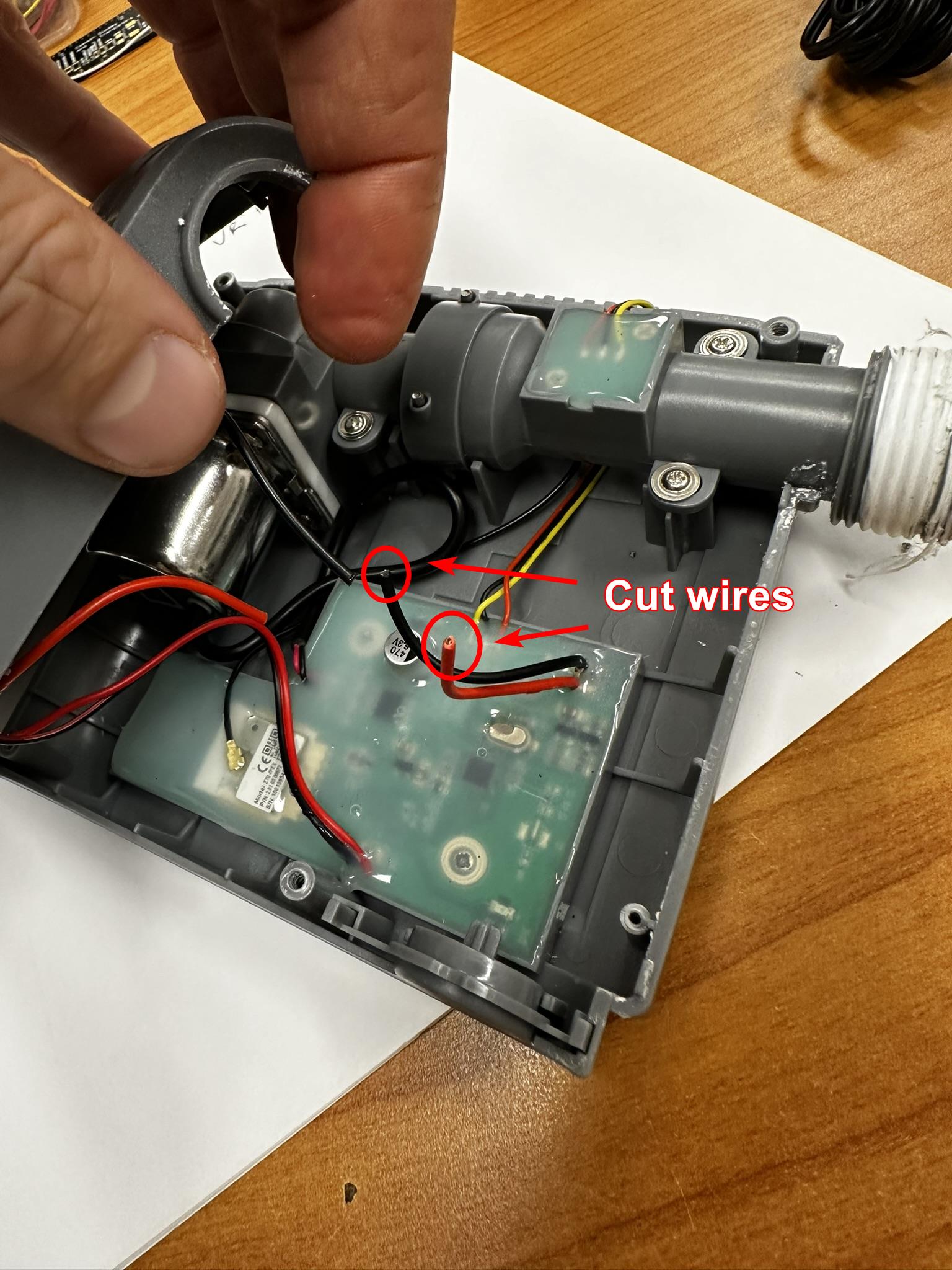
5.3 Cut the Power and GND wires
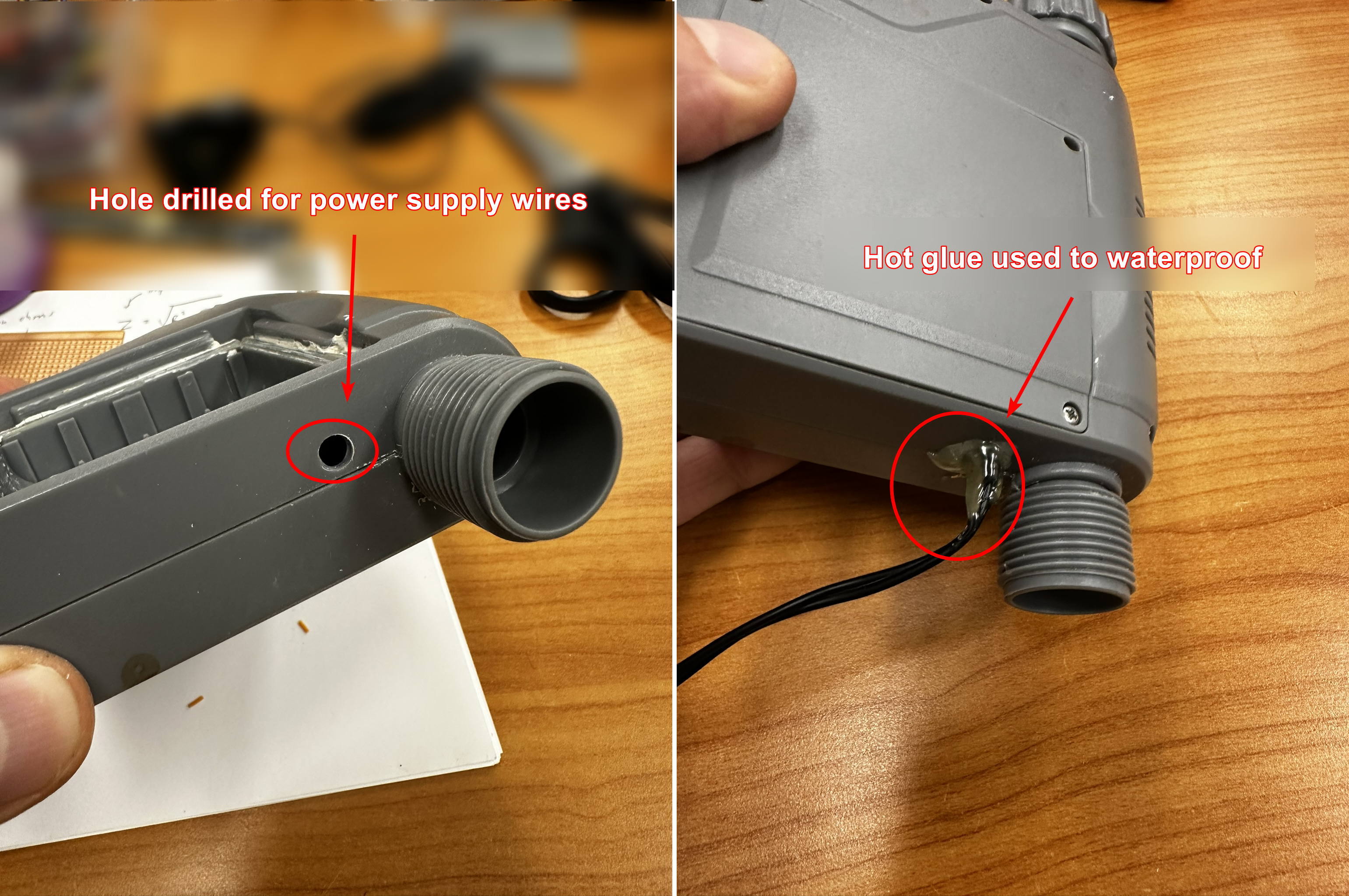
Cut the power and gnd wires and solder longer wires so there is enoug length to poke through a hole in the
5.4 Modifying the device
Modify the device to accommodate the regulated power supply or store the power supply in it’s own plastic container. This step may involve rewiring and integrating the new power source seamlessly.
5.5 Assembling the System
Put everything back together, ensuring all components are properly connected. I found that the best way to do this was using a drill to cut a small hole in the side of the plastic housing and poking the new power supply wires through the housing that way. You can use hot glue or silicon to make the housing waterproof again :)